Mechanical Engineering
Bachelor's degree at UNIFEG (2022–2026), in its final stage, focused on CAE pre-processing and finite element meshing.
Mechanical Engineering.CAE Pre-processing.FEA Meshing.
I prepare finite element models and meshes for durability analyses in the automotive industry, from clean geometry in HyperMesh to a simulation-ready model.
01 · About me
I'm in the final stage of a Mechanical Engineering degree at UNIFEG and, since May 2025, I've been working with CAE at TC Projetos, preparing finite element models for major automotive brands. My focus is pre-processing: cleaning up geometry, building 2D/3D meshes in Altair HyperMesh and making sure every element meets quality standards. From the first geometry cut to the last quality check, I treat every mesh as the foundation of a reliable result.
Bachelor's degree at UNIFEG (2022–2026), in its final stage, focused on CAE pre-processing and finite element meshing.
Mechanical Engineering: Bachelor's degree at UNIFEG (2022–2026), in its final stage, focused on CAE pre-processing and finite element meshing.
Journey
UNIFEG
Started the Mechanical Engineering degree.
TC Projetosnow
CAE pre-processing internship since May 2025.
Graduation
Mechanical Engineering, with a thesis on an AI-generated swingarm evaluated by finite elements against the Yamaha YZF-R1 one.
✓ assembly complete · 3 parts, 2 bolts
02 · Process
From sketch to validated part, each stage sets up the next. Drag the control and follow the part through each stage; in the simulation, pull the tip of the beam to apply load.
resultsshown in the Simulation stage
ASTM A36 steel · E = 200 GPa · σy = 250 MPa · bar 20×40 mm · L = 500 mm · deformation ×20
01 · Idea
A real problem, a notebook and lots of questions. The points are still loose: time to understand what needs to exist.
03 · Mesh Quality
In pre-processing, every element goes through quality checks before reaching the simulation. One of the nodes is misplaced: drag the inner nodes (or use the arrow keys) and watch the criteria react.
click an element to inspect it
6/9 passed
1 failed element: this model can't go to simulation.
Element E3 · QUAD4
failed| Criterion | Value | Limit |
|---|---|---|
| Aspect ratio | 1.35 | < 5 |
| Skew | 20.8° | < 60° |
| Jacobian | 0.59 | > 0.6 |
| Min angle | 65.4° | > 45° |
| Max angle | 138.4° | < 135° |
idealcould be betterwarningfailedWarpage does not apply here: the patch is flat (2D). Typical pre-processing limits; each project defines its own.
drag to rotate · hover the nodesdrag to rotate · tap the nodes
Element types
CHEXA (hex8) · 3D solid
The most accurate and efficient solid, but it requires splitting the geometry into blocks to mesh by sweeping or mapping. More work, better result.
1st Straight edges: displacement varies linearly between nodes.
qualitative comparison
04 · Thesis
To what extent can generative AI, combined with HyperMesh and finite element analysis, deliver a lighter swingarm without compromising its stiffness and structural strength?
Mechanical Engineering · UNIFEG · 2026 · co-authored with Gustavo Henrique Rezenda da Rocha · advisor: Prof. Valdoel da Silva Junior
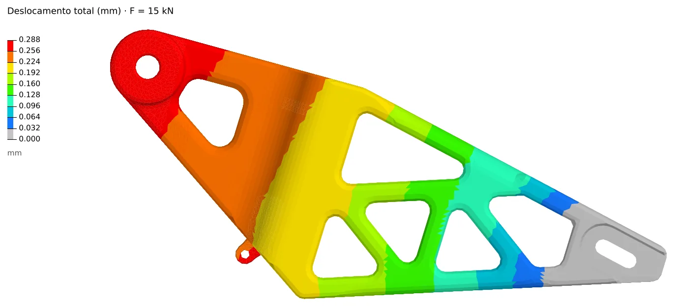
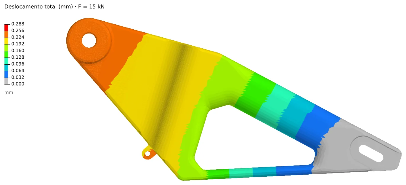
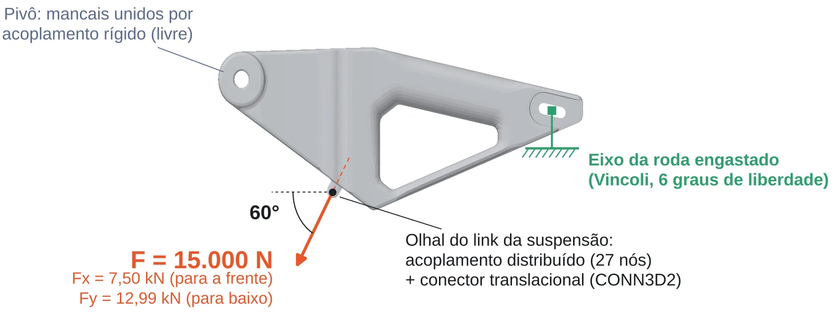
Total displacement under 15 kN at the eyelet, at 60°: 0.231 mm for the reference and 0.262 mm for the AI version.
−9.3%
mass
19.27 → 17.48 kg
−11.6%
eyelet stiffness
64.8 → 57.3 kN/mm
−7.9%
peak von Mises
104 → 96 MPa
1.6 → 5.2
safety factor
yield, driven by the alloy
Workflow
Mesh quality
| Metric | Criterion | Yamaha | AI |
|---|---|---|---|
| C3D4 elements | 261,684 | 252,507 | |
| Nodes | 54,251 | 53,412 | |
| Median edge | 6.1 mm | 6.0 mm | |
| Aspect ratio | ≤ 5.0 | 99.995% | 99.98% |
| Tet collapse | > 0.2 | 100% | 100% |
Same size and same quality in both models: that is what makes the comparison fair. In C3D4 the Jacobian is constant and equal to 1.
Conclusion
Generative AI quickly delivered a lighter swingarm with the same mounting points, but no efficiency gain: it removed material and lost stiffness in the same proportion. The limit is stiffness, not strength. To truly optimize, the AI shape should feed a load-driven topology optimization.
Next steps: all five load cases, C3D10 with a convergence study, fatigue analysis and a bench prototype.
05 · Portfolio
CAE pre-processing and finite element meshing, from my thesis to the automotive industry.
06 · Contact
Guaxupé, MG · open to opportunities in CAE and pre-processing